Thursday 4 September 2014

SCR Based SSS Solar Charge Control

                            SCR Based SSS Solar Charge Control

     A force-commutated SCR makes a novel Solid State Switch in a solar charge regulator control. Prior art includes relay and transistor switches, but an SCR switch in this type of DC application may be new to the world (normally SCRs are applied in line-commutated AC applications). Advantages include robustness and the requirement of only one conductive device that performs (3) functions: switch, latch and reverse polarity diode (reverse blocking thyristor). The main SCR conducts the charging current from the solar panel to the battery while a 2nd commutation SCR performs the function of commutating (turning off) the main SCR current at the end of the conduction period. All circuitry consists of readily available discrete components. Note that this is old technology and may not be the best or cheapest solar charge control solution, but it makes a great, mind-expanding tech school lab experiment.Programmable Unijunction Transistor Gate Drivers

Both the main and commutation SCRs have their gates driven by PUT (Programmable Unijunction Transistor) circuits. Advantages are high gate drive current (100mA peak), fast pulse rise-time and Schmitt Trigger type of operation. Q1 is a free-running oscillator that outputs pulses every 6seconds. Q2 is a similar circuit that is inhibited when the main SCR is blocking (no commutation function needed when the SCR is not conducting). Q2 receives its charge signal from the voltage regulator transistor Q6.

Voltage Reference

A TL431 is strapped to regulate at its minimum voltage of 2.5V. R19 biases it at about 1mA. It is referenced to the positive battery terminal. This is far superior to a low voltage zener because it has very low dynamic resistance and low thermal temperature coefficient.

Voltage Comparator

Q6 is a PNP transistor that performs the function of voltage comparator. It compares the output of the feedback voltage divider from the battery with the 2.5V reference. As the battery voltage increases beyond this threshold, the transistor collector current increases thus charging C4 more rapidly and reducing the conduction period that is controlled by Q5. While a bipolar transistor has a Vbe that is temperature dependent, it tends to track the battery voltage that is also temperature dependent. No attempt was made for accurate temperature compensation.

Commutation capacitor

Commutation capacitor C3 is rather large. I used a 2uf, 50V film type in my low current evaluation circuit. 70uf may be built up by paralleling a number of capacitors or an electrolytic capacitor may be evaluated –I did not test operation with an electrolytic. The oscilloscope indicated a reverse polarity spike across the capacitor, so I initially thought that an un-polarized capacitor would be best –however, the voltage transient may not be a real issue.

SCR turn-off time

The S2800A has a 50uS turn-off time specification. This is typical of many SCRs. To ensure that this period was exceeded, I sized the commutation capacitor for 100uS or so. (See oscillographs.) Actually, I found that my SCRs would commutate 200mA reliably in 25uS. However, that was a low current –at high currents, SCRs require additional time for the charge to dissipate. Years ago before the advent of high voltage MOSFETs and IGBTs high-speed SCRs were available –some were specified as low as 5uS thus greatly reducing the size of the commutation capacitor.

Minimum conduction period

The commutation capacitor charges via R7 to 12V with an R-C of approx 200mS. This generally indicates that the minimum conduction period must exceed about 200mS or C3 may not have sufficient charge to commutate the main SCR. However, I experienced no problems. By increasing the value of R16, the minimum conduction period may be increased.

Holding current

It is possible that SCR2 may not turn off due to low holding current –this conducts through R7. Devices may be selected for a holding current exceeding 4mA, or higher if R7 is reduced. However, even if it remains on, the main SCR will commutate the commutation SCR at the beginning of the conduction period because the circuit is essentially symmetrical.

LED function

D1 prevents reverse voltage across LED D2. Q2 & 3 invert the LED function so that the red LED is on when the green LED is off and vice-versa. Note that the LEDs are powered by the solar panel so that they extinguish when the solar panel is inactive. Q4 turns off Q5 when the main SCR is blocking.

Oscillographs


Wednesday 3 September 2014

Why the Direction of Rotation of a TABLE Fan & CEILING Fan is different?

■ Question: Why the Direction of Rotation of a TABLE Fan &
CEILING Fan is different?

■ Answer: In table fan rotor is rotating part, but in ceiling fan stator is rotating part, so the direction of rotation is different. Transformer is not rotating because for rotating magnetic field is required which is produced only when the current is passed through the windings which are displaced physically by 120degrees and phase difference of 120 degrees where as in transformer there is no physical displacement of 120degrees hence transformer cannot rotate.

■ Question:
Why we use a capacitor in an electric fan?

■ Answer:
1. Capacitor is used for both starting the electric fan and improving power factor.

2. The voltage taken by the fan during running has lagging power factor and in order to run the fan we need leading power factor. The capacitor increases the power factor. So we use capacitor in fan to increase its power factor

3. to give a quick start-up for any instrument, capacitor is used in electronics, by using capacitor in the start-up there is a charge accumulation in between the plates of capacitor,which is discharged again and gives a quick start to the instrument otherwise we have to use a very high voltage to the instrument. 

What is the difference between AC and DC Resistance & How to calculate it?

What is the difference between AC and DC Resistance & How to calculate it?

Resistance 

The property of a substance or material which oppose the flow of electricity through it is called resistance OR,
Resistance is the ability of a circuit or element (which is called resistor) to oppose current.
Examples of Resistors with the ability of high resistance are Wood, Air, Mica, Glass, Rubber, Tungsten etc.
Unit of Resistance is “Ohm” and it is denoted by ? and it is represented by “R”.
difference between AC and DC Resistance
AC Resistance
In Simple words, Resistance in AC circuits is called Impedance. Or
The Overall resistance (Resistance, Inductive reactance and Capacitive reactance) in AC circuits is called Impedance (Z).
Explanation:
When AC Current pass through a wire (resistor, inductor), then current produces a magnetic field across that wire which opposes the flow of AC Current in it along with the resistance of that wire. This oppose cause is called Inductance or Inductance is the property of Coil (or wire) due to which opposes any increase or decrease of current or flux through it. Also, we know that inductance is only exist in AC because the magnitude of current continuously changing
Inductive Reactance XL, is the property of Coil or wire in an AC circuit which opposes the change in the current. The unit of Inductive reactance is same as Resistance, capacitive reactance i.e. Ohm (?) but the representative symbol of capacitive reactance is XL.
Likewise,
Capacitive Reactance in a capacitive circuit is the opposition to current flow in AC circuits only. The unit of capacitive reactance is same as Resistance, Inductive reactance i.e. Ohm (?) but the representative symbol of capacitive reactance is XC.
Measuring AC Resistance
Electrical Resistance & Impedance Formulas in AC Circuits
In AC Circuits (Capacitive or inductive Load), Resistance = Impedance i.e., R = Z
Z = v (R2 + XL2)… In case of Inductive Load
Z = v (R2 + XC2)…In case of Capacitive Load
Z = v (R2 + (XL- XC)2…In case of both inductive and capacitive Loads.
*Good to know:
Where;
XL = Inductive reactance
XL = 2pfL…Where L = Inductance in Henry
And;
Xc = Capacitive reactance
Xc = 1/2pfC… Where C = Capacitance in Farads.
DC Resistance
We know that there is no concept of Inductive and Coactive reactances in DC Circuits. i.e. capacitive and inductive reactances in DC circuits zero  because there is no frequency in DC circuits, i.e. magnitude of DC current is constant. Therefore, only the original resistance of wire comes into play.
Good to know:
That’s why the resistance offered by a wire is lower for DC than AC.
Measuring DC Resistance
Electrical Resistance Formulas
In DC Circuits, we calculate the resistance by Ohm’s Law.
R = V/I.
Good to Know:
When solving electric circuits for finding resistance and you are not sure which one should you take into account whether  AC or DC resistances, then, if the current passed is AC, then take AC resistance else if the current passed is DC, take DC resistance.

diode_circuit_symbols


Working of Electrical Interlocking

Working of Electrical Interlocking

When we push the ON-1 button to energies the M1 Contactor (or starts M1 Motor), then circuit complete through Fuse, Overload relay’s trip link, OFF Push -1 and ON Push 1. And motor M1 Starts to run.
As Contactor M1 energies, it’s all normally Close (NC) links open and the other normally open (NO) links used in the circuit close. 
When m1 energies, the normally open (NO) link will be closed immediately, which is in parallel with ON-Push 1. This is called Holding link i.e. it holds the motor in start condition. Now, Motor will still run even we leave (disconnect to stop) the ON-Push 1.
A normally open (NO) link is also used in line 2. When M1 energizes, this link (NO M1 in line 2) will be also closed, therefore, M1 Motor will start to run, this way, supply also will reach to ON Push 2. Now, if we press ON-Push 2, then second motor M2 will be also started to run, in addition, the normally open (NO) links of the connected contactor M2 in the circuit would be also closed immediately. And Holding would be occurred through M2 link which is in parallel with ON-Push 2. This way, Motor 2 will start to run.
Note that Motor 2 will not start to run until Motor 1 runs, i.e. unless Motor 1 link M1 close. Likewise, Motor 3 will not start until motor 2 runs, i.e. motor 3 will start (by pressing the On-Push of Motor 3 =M3) to run after start the motor 2.
In each control circuit, control fuse, and overload relays are connected for short circuit and overload protection respectively.

you may also read:
The Star-Delta (Y-?) 3-phase Motor Starting Method by Automatic star-delta starter with Timer.
Three Phase Motor Connection STAR/DELTA Without Timer Power & Control Diagrams
Modification in the Electrical Interlocking Control Circuit
This is a simple electrical interlocking circuit. Lots of circuits similar to this interlocking circuit are used in industries. The circuit interlocking depends on the nature of working and task which is to be done by motors. So we may use and make any kind of interlocking circuits for any purpose very easily. 
In short, we may change the motors operation and control by doing some modification in the above simple electrical interlocking control circuit diagram. For example, if we need that Motor 1 should stop when Motor 3 starts to run, then we may use a Normally Close (NC) link of M3 in line 1. This way, when Contactor M3 energizes, and motor 3 starts to run, then the normally close (NC) link of Motor 1 connected in line 1 will open immediately (after energizing the M3 Contactor) which cause to de-energize the M1 contactor, hence, Motor M1 will stop.
We may also configure the above electrical interlocking control circuit with little modification for star and run each motor individually. 
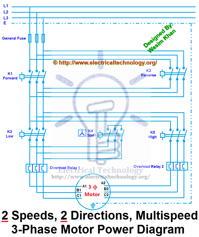
Three phase induction motors runs with two speeds 1 direction and two speeds two directions motor control and induction motors reverse forward operation is the types of electrical interlocking. 
Below is another electrical interlocking control circuit diagram.

Electrical Electronics Engineers


some intresting pics about EEE


Tuesday 2 September 2014